Scheduled Downtime
On Friday 21 April 2023 @ 5pm MT, this website will be down for maintenance and expected to return online the morning of 24 April 2023 at the latest

Higher order advection and grid number?

This post was from a previous version of the WRF&MPAS-A Support Forum. New replies have been disabled and if you have follow up questions related to this post, then please start a new thread from the forum home page.

yhwong

New member
I am running WRF SCM and the README file states that the WRF SCM "runs on a 3x3 stencil with periodic lateral boundary conditions in X and Y." I am wondering why is a 3x3 stencil used instead of just 1x1, as most SCM assumes? I tried changing the namelist option to run a 1x1 SCM, and it failed. However, 2x2 works.

I am wondering if this has to do with the way WRF numerical computation works, specifically the computation of higher order advection. As WRF allows up to the 6th order advection, I wonder if this is why there is a requirement for the minimum number of grid? Would someone be able to enlighten me to this?

Thank you!
 
This is related to the specific WRF code structure. 3x3 grids is the smallest number of grids that can be implemented in WRF. This is how SCM can be embedded in the WRF code system.
 
Hi Ming Chen,

I want to know the computation stencil of WRF. You say "3*3 grids is the smallest number of grids that can be implemented in WRF" and "it is related to the specific WRF code structure". Where can I get more details about your words? What is more, I know that WRF allows several order advection. How this order related to WRF computation stencil?

Thank you very much!!
 
Hi,
Your question is essentially about the dynamics core of WRF. We have several documents that provide detailed description of dynamics including the advection options. Please take a look at the document here:
https://www2.mmm.ucar.edu/wrf/users/docs/technote/v4_technote.pdf
More details about advection options can be found here:
https://www2.mmm.ucar.edu/wrf/users/tutorial/presentation_pdfs/201907/skamarock_dynamics.pdf
Hope these information is helpful for you to understand the computation stencil of WRF.
 
Hi Ming Chen,

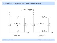
Thanks for your early reply! I have read the description file for version 3 and I know that C-grid staggering is used in WRF like this. But I still have no idea about its computation stencil. If I choose 5 order advection schemes for all dimensions, why it is not 6 points stencil? or 6+6+6=18 points stencil? This has confused me for a very long time. I will appreciate it if you can give me some ideas!

Thank you again!!
 

Attachments

  • C-grid staggering in wrf.jpg
    C-grid staggering in wrf.jpg
    80.3 KB · Views: 650
Good question!

Due to the WRF staggering, a 1x1 grid is not possible. Since WRF uses an Arakawa-C grid, a minimum domain would be 2x2. This 2x2 would be sufficient for the U and V momentum cell faces to be defined, and for a single mass point (cell-centered) location for fields such as moisture, pressure, temperature, and all of the physics fields.

I would suggest running your 2x2 domain and comparing those results to a 3x3 domain. Use an un-optimized build of the the WRF model (./configure -d), which should provide bitwise identical results, IF these are actually giving the same answers.

Let us know what you find. The recommendations for 3x3 (for the SCM) and 3-momentum points wide (for the 2d cases) have been in place for more than 12 and 20 years, respectively.
 
Top