Scheduled Downtime
On Friday 21 April 2023 @ 5pm MT, this website will be down for maintenance and expected to return online the morning of 24 April 2023 at the latest

Segmentation fault RRTMG with adaptive time step.

Hi, from all tests you have done, at this point, I would be pretty surprised if it comes out that the reason for simulation failures is not the PBL choice. It seems we will know soon :) Good luck!
 
Hi, from all tests you have done, at this point, I would be pretty surprised if it comes out that the reason for simulation failures is not the PBL choice. It seems we will know soon :) Good luck!
Hi Meteoadriatic,

I’ve been trying to use the YSU scheme as the PBL parameterization (instead of QNSE I was using), but WRF continues to stop unexpectedly without any clear explanation. The simulation halts without generating a segmentation fault or a similar error. Below is an excerpt from the rsl.error file showing the output just before it stops.

The only way I’ve managed to make it work is by further reducing the target CFL value. For example, with target_cfl = 0.2, the simulation stops at 2017-02-20_08:38:37. If I set target_cfl to 0.5, it stops immediately after reaching 2017-02-20_02:00:00. So I keep same parameter for adaptive time step as previous test.

Timing for main (dt= 0.12): time 2017-02-20_08:38:37 on domain 5: 0.06947 elapsed seconds
d05 2017-02-20_08:38:37+**/** Top of Radiation Driver
Timing for main (dt= 0.12): time 2017-02-20_08:38:37 on domain 5: 0.05946 elapsed seconds
d05 2017-02-20_08:38:37+**/** Top of Radiation Driver
...
Timing for main (dt= 0.03): time 2017-02-20_08:38:37 on domain 5: 0.07061 elapsed seconds
d05 2017-02-20_08:38:37+**/** Top of Radiation Driver


Here is the only thing I change in namelist.input :

bl_pbl_physics = 1, 1, 1, 1, 1,
sf_sfclay_physics = 1, 1, 1, 1, 1,

Since the simulation always stops right after showing "Top of Radiation Driver," I suspect the issue might be related to the radiation scheme. Could you confirm if this is indeed the case?

Also, do you think YSU is a suitable choice for simulations at a 1/9 km resolution? It seems to me that it is a good and straightforward PBL parameterization. For reference, I change the sf_sfclay_physics setting when switching to YSU.

Thanks for your help!
 
Last edited:
Hello,
Well, I'm surprised to hear this.

I'm not sure that radiation scheme is the source of the problem; might be but also might not - it might crash because of unrealistic state of the model at that particular point in time. And that is the way to go with debugging I think. Can you set wrfout frequency so that it dumps model state right before the crash, the closer to the crash, the better, and then look into it and see if there is anything unrealistic? That might guide you toward the solution.

For such small grids, instead of YSU, you would probably be better with scale aware schemes (Shin-Hong or SMS-3DTKE) or LES setup.
Hi Meteoadriatic,

I will try also SMS-3DTKE, when turning off pbl scheme.

After modifying the frequency while keeping YSU as the PBL scheme, I noticed an unusual pattern in most variables (T2, P, W, U, V). Specifically, there’s a localized spot showing significantly higher values for W. This typically occurs near the highest summit in my third domain, where the slope appears to be quite steep.

But when using QNSE as previously, I saw nothing on wrfout files.

To address this, I’m planning to directly smooth the topography in that area, especially around this location, and observe the results.
 
Last edited:
Hello,
Oh, in that case the too steep slope could very likely be the cause of crashes and smoothing will help!
Hi,

I attempted to smooth the topography, and while it allowed the model to run longer compared to the unsmoothed version, it extended the runtime significantly—producing wrfout files for 30 hours instead of just 9 hours. I used my standard setup with five domains, the QNSE PBL scheme, default USGS land use, WRF version 4.6.1, and adaptive time stepping. To ensure the simulation could run for an extended period, I set a small target_cfl value of 0.2 for all domains.

Despite these adjustments, the error still occurs at a specific point, showing the following message:

d05 2017-02-21_06:20:53+**/** RRTMG LW CLWRF interpolated GHG values year: 2017 julian day: 51.26451
d05 2017-02-21_06:20:53+**/** co2vmr: 4.062334790387511E-004 n2ovmr: 3.284720907739753E-007
ch4vmr: 1.864612663469318E-006 cfc11vmr: 3.065397540727884E-010
cfc12vmr: 4.977012290951540E-010
Caught signal 11 (Segmentation fault: address not mapped to object at address 0xffffffe02f2fb560)


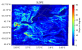
While smoothing the topography helps to some extent, I had to apply significant smoothing, even though the initial slopes were not particularly steep. Specifically, I smoothed slopes greater than 25°. Below is the slope of my inner domain, which has a high resolution of 1/9 km:
Slope_Cadarache_domain.png


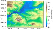
As you can see, the steepest slopes are located in the left-middle and bottom portions of the domain. These correspond to two key areas: the first marks the entrance to a valley, and the second is the highest summit, which is only 650 meters tall.

I also tested whether using a single node for the simulation could mitigate the issue, as it seems increasingly related to memory leakage. However, this approach resulted in a new error, distinct from the previous one, but now occurring at the time step defined for the cumulus option. The error message is as follows:

Caught signal 11 (Segmentation fault: address not mapped to object at address 0x7ffef7067000)
==== backtrace (tid:1767100) ====
0 0x0000000000012cf0 __funlockfile() :0
1 0x0000000002b1e752 module_cu_kfeta_mp_kf_eta_para_() ???:0
2 0x0000000002b1640e module_cu_kfeta_mp_kf_eta_cps_() ???:0


Just in case, here how my domains topography looks like for my inner domain that is the problem here :

Topo.png

The next step I plan to take is to stop using the bl_pbl_physics option and instead try the km_opt option, as you suggested, with the SMS-3DTKE scheme. Additionally, I have already shared my setup and input files (wrfinput) with Kwerner to see if it is possible to reproduce the same error and potentially provide further insights into the issue.

Thank you again for all your suggestions and support!
 
Hello,
I think that 40 degree slope is too much. From literature it looks it depends on vertical distance between model levels, too:

"These predictions nearly match what is found in practice by trial and error: one needs dz > 32 m for max slope = 42° and dz > 25 m for max slope = 28° to keep the WRF model numerically stable (see Section 3.3)."

You defined eta levels yourself, see real output to check how dense they are, that is, what is the mininum vertical distance between your two nearest levels. And compare with quoted findings in that paper ....

Maybe this helps!
Hi,

I wanted to share some insights regarding the smoothing of topography in my simulations. The approach I am using aligns with the methodology presented in this article. I am currently working under the supervision of Pr. Staquet, who is a co-author of the paper alongside Le Bouédec. I am utilizing their code to smooth the topography for my simulations, including the one over Grenoble mentioned in the article.

For context, my simulation over Grenoble required this smoothing, particularly at slopes of 42°, due to the steep and complex terrain in that region.

For the current simulation I conducted using WRF, which is located south of Grenoble in Cadarache, the terrain is less complex. I applied the same smoothing code but adjusted the slope parameter to 25° instead of 42°, as the default setting did not sufficiently smooth the terrain in this case, unlike in Le Bouédec's work.

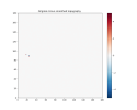
Below is the result of smoothing with the 42° parameter. It shows, as in the paper, the difference between the original and smoothed topography. As you can see, the steepest slopes remain largely unsmoothed or are only smoothed at specific points!
DiffTopo_42.0_111.111_n1.0_p1.0.png
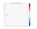
Now this is what I obtain with 25°. If you look at previous topography image of slope and topography, you see that is smooth much more the actual steepiest slope for my simulation :

DiffTopo_25.0_111.111_n1.0_p1.0.png
 
At this point, I would like to summarize the steps I have taken so far:

Initial Issue​

I initially encountered a segmentation fault while using the adaptive time step, even with small target CFL values and other recommended parameters. The error occurred at the time step (every 10 minutes in this case) of the long-wave radiation scheme (RRTMG). A typical error message looked like this:

Code:
RRTMG LW CLWRF interpolated GHG values year: 2017 julian day: 51.26451

co2vmr: 4.062334790387511E-004 n2ovmr: 3.284720907739753E-007
ch4vmr: 1.864612663469318E-006 cfc11vmr: 3.065397540727884E-010
cfc12vmr: 4.977012290951540E-010
Caught signal 11 (Segmentation fault: address not mapped to object at address 0xffffffe02f2fb560)

This issue occurred primarily with my initial setup, which included:

  • 3 domains with a 1:9 nesting ratio (9 km / 1 km / 111.111 m)
  • QNSE PBL physics
  • Corine Land Cover land use with a custom table for compatibility
  • WRF version 4.4.2

Steps Taken to Address the Issue​

1. Standardizing Domain Ratios and Setup​

I adopted a 1:3 domain ratio with 5 domains (9 km / 3 km / 1 km / 333 m / 111 m) as per WRF recommendations.

  • Switched to WRF version 4.6.1
  • Replaced Corine Land Cover with USGS default land use (24 classes)
Despite these changes, the model still crashed for the same reason after producing 9 hours of output.

2. Adjusting Radiation Time Step and Adding w_damping​

  • Set the radiation time step (radt) to 9 minutes instead of 10.
  • Experimented with various other radt values and activated the w_damping option.
However, the simulation still failed for the same reason, producing less than 9 hours of output.

3. Changing PBL Scheme​

  • Removed QNSE and tested the YSU PBL scheme.
  • This resolved the segmentation fault but introduced a new issue: instabilities due to CFL errors, as detected in the rsl files, even with a small target CFL of 0.2.
This approach also proved unsuccessful.

4. Smoothing Topography​

I applied topography smoothing and observed an improvement: the simulation ran for 30 hours instead of the usual 9 hours. However, the same segmentation fault eventually returned.

5. Adjusting Node Configuration​

I tested running the simulation on a single node with full memory allocation. This resulted in a different issue:

  • A segmentation fault occurred in the cumulus scheme (cu_physics), resembling the RRTMG LW segmentation fault.

6. Testing New Configurations​

I am now exploring the following:

  • Disabling PBL parameterization entirely (bl_pbl_physics = 0) and using km_opt = SMS-3DTKE, both with and without topography smoothing.
  • Applying additional smoothing to the topography and revisiting the original setup with QNSE PBL active.

For now, the only thing that help but with expensive cost for computation time, is using small constant time step (turn off adaptive time step), typically of 5-10s for first domain. But this is potentially not universal and based on different period it can probably give back the same error. I was arriving wth my initial setup thought.

**I used chatgpt to restructure the ideas and have good listing.**
 
Last edited:
At this point, I would like to summarize the steps I have taken so far:

Initial Issue​

I initially encountered a segmentation fault while using the adaptive time step, even with small target CFL values and other recommended parameters. The error occurred at the time step (every 10 minutes in this case) of the long-wave radiation scheme (RRTMG). A typical error message looked like this:

Code:
RRTMG LW CLWRF interpolated GHG values year: 2017 julian day: 51.26451

co2vmr: 4.062334790387511E-004 n2ovmr: 3.284720907739753E-007
ch4vmr: 1.864612663469318E-006 cfc11vmr: 3.065397540727884E-010
cfc12vmr: 4.977012290951540E-010
Caught signal 11 (Segmentation fault: address not mapped to object at address 0xffffffe02f2fb560)

This issue occurred primarily with my initial setup, which included:

  • 3 domains with a 1:9 nesting ratio (9 km / 1 km / 111.111 m)
  • QNSE PBL physics
  • Corine Land Cover land use with a custom table for compatibility
  • WRF version 4.4.2

Steps Taken to Address the Issue​

1. Standardizing Domain Ratios and Setup​

I adopted a 1:3 domain ratio with 5 domains (9 km / 3 km / 1 km / 333 m / 111 m) as per WRF recommendations.

  • Switched to WRF version 4.6.1
  • Replaced Corine Land Cover with USGS default land use (24 classes)
Despite these changes, the model still crashed for the same reason after producing 9 hours of output.

2. Adjusting Radiation Time Step and Adding w_damping​

  • Set the radiation time step (radt) to 9 minutes instead of 10.
  • Experimented with various other radt values and activated the w_damping option.
However, the simulation still failed for the same reason, producing less than 9 hours of output.

3. Changing PBL Scheme​

  • Removed QNSE and tested the YSU PBL scheme.
  • This resolved the segmentation fault but introduced a new issue: instabilities due to CFL errors, as detected in the rsl files, even with a small target CFL of 0.2.
This approach also proved unsuccessful.

4. Smoothing Topography​

I applied topography smoothing and observed an improvement: the simulation ran for 30 hours instead of the usual 9 hours. However, the same segmentation fault eventually returned.

5. Adjusting Node Configuration​

I tested running the simulation on a single node with full memory allocation. This resulted in a different issue:

  • A segmentation fault occurred in the cumulus scheme (cu_physics), resembling the RRTMG LW segmentation fault.

6. Testing New Configurations​

I am now exploring the following:

  • Disabling PBL parameterization entirely (bl_pbl_physics = 0) and using km_opt = SMS-3DTKE, both with and without topography smoothing.
  • Applying additional smoothing to the topography and revisiting the original setup with QNSE PBL active.

For now, the only thing that help but with expensive cost for computation time, is using small constant time step (turn off adaptive time step), typically of 5-10s for first domain. But this is potentially not universal and based on different period it can probably give back the same error. I was arriving wth my initial setup thought.

**I used chatgpt to restructure the ideas and have good listing.**

I decided to stop using PBL parameterization and instead switched to the SMS-3DTKE scheme. However, similar to when I changed the PBL parameterization in the past (e.g., with YSU), I encountered the same issue: the simulation abruptly stops at the 3-hour mark without producing a segmentation fault or error message.

In contrast to the earlier tests with PBL schemes like YSU, this time there are no CFL-related errors, even though I’ve kept the target CFL value low (0.2). This makes the root cause less clear.

So far, neither turbulence nor PBL parameterization seems to resolve the original issue. In fact, switching to the SMS-3DTKE scheme appears to have made the problem worse.
 
Good day,

Have you tried to use default vertical level spacing, i.e. commenting out eta_levels(1:46) entry?
Hi,

Sorry for the delay. No I didn't try it, but I doubt that it will change something as I use custom 45 eta levels. Recently I saw that I was not using ulimit -s unlimited corretly and also I try putting time_step_sound at 10 for every domain and I will see if it change something but apparently ulimit is not solving the initial issue.
 
Hello,
I would try, because, take a look at your first few levels

1.0000, 0.9987, 0.9974, 0.9962, 0.9949, ...

Here are mine, using automatic algorithm, 57 levels total, 1.220 dzstretch_s and dzbot = 40m:
1.0000, 0.9950, 0.9891, 0.9820, 0.9736, ...

To be honest this is huge difference in levels density near ground. I'm really not surprised that you can't have good time step with such spacing. Please try automatic spacing.
 
Top