stormchasegenie
Member
Greetings,
I am using WRF4.1.3 to dynamically downscale a GCM. I am using 45-km wrfout files to drive a 9-km simulation using one-way nesting. Ndown is used to generate the wrfbdy and wrfinput files for the 9-km experiment using the 45-km wrfout files.
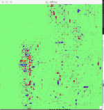
I have successfully completed the above procedure on dozens of occasions, however this time something strange is happening. Granted, my current grid configuration is different compared to my previous projects. Specifically, the new wrfinput_d02 file that is created contains a zone approximately 10 gridpoints thick where it appears that the terrain height from the d01 grid is being mapped (see attached screen grab of the difference plot). This band is circumnavigating most of but not all of the lateral boundary. Additionally, the old wrfinput_d01 and old wrfinput_d02 files are both created for the same date. However, there are differences in variables such as T2 between the wrfndi_d02 and new wrfinput_d02 files (see attached screen grab). This has never been the case for my previous downscaling ventures that made use of ndown. When initializing on the same date, the T2 map for instance was identical in the met_em*, wrfinput_d01, new wrfinput_d02, and wrfndi_d02 files. The met_em files look as they should. Attached also is my defined grids. In the postscript, I have added potentially useful namelist.input variables and compilation/configuration options.
Any thoughts are appreciated.
Thanks so much,
Interesting namelist.input variables:
&domains
i_parent_start = 1, 46,
j_parent_start = 1, 24,
s_we = 1, 1,
s_sn = 1, 1,
e_we = 110, 256,
e_sn = 95, 261,
smooth_cg_topo = .true.,
&bdy_control
spec_bdy_width = 5,
specified = .true.
&namelist_quilt
nio_tasks_per_group = 0,
nio_groups = 1,
I am using WRF4.1.3 to dynamically downscale a GCM. I am using 45-km wrfout files to drive a 9-km simulation using one-way nesting. Ndown is used to generate the wrfbdy and wrfinput files for the 9-km experiment using the 45-km wrfout files.
I have successfully completed the above procedure on dozens of occasions, however this time something strange is happening. Granted, my current grid configuration is different compared to my previous projects. Specifically, the new wrfinput_d02 file that is created contains a zone approximately 10 gridpoints thick where it appears that the terrain height from the d01 grid is being mapped (see attached screen grab of the difference plot). This band is circumnavigating most of but not all of the lateral boundary. Additionally, the old wrfinput_d01 and old wrfinput_d02 files are both created for the same date. However, there are differences in variables such as T2 between the wrfndi_d02 and new wrfinput_d02 files (see attached screen grab). This has never been the case for my previous downscaling ventures that made use of ndown. When initializing on the same date, the T2 map for instance was identical in the met_em*, wrfinput_d01, new wrfinput_d02, and wrfndi_d02 files. The met_em files look as they should. Attached also is my defined grids. In the postscript, I have added potentially useful namelist.input variables and compilation/configuration options.
Any thoughts are appreciated.
Thanks so much,
Interesting namelist.input variables:
&domains
i_parent_start = 1, 46,
j_parent_start = 1, 24,
s_we = 1, 1,
s_sn = 1, 1,
e_we = 110, 256,
e_sn = 95, 261,
smooth_cg_topo = .true.,
&bdy_control
spec_bdy_width = 5,
specified = .true.
&namelist_quilt
nio_tasks_per_group = 0,
nio_groups = 1,